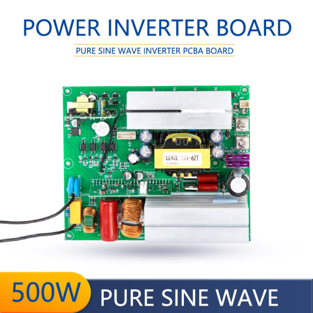
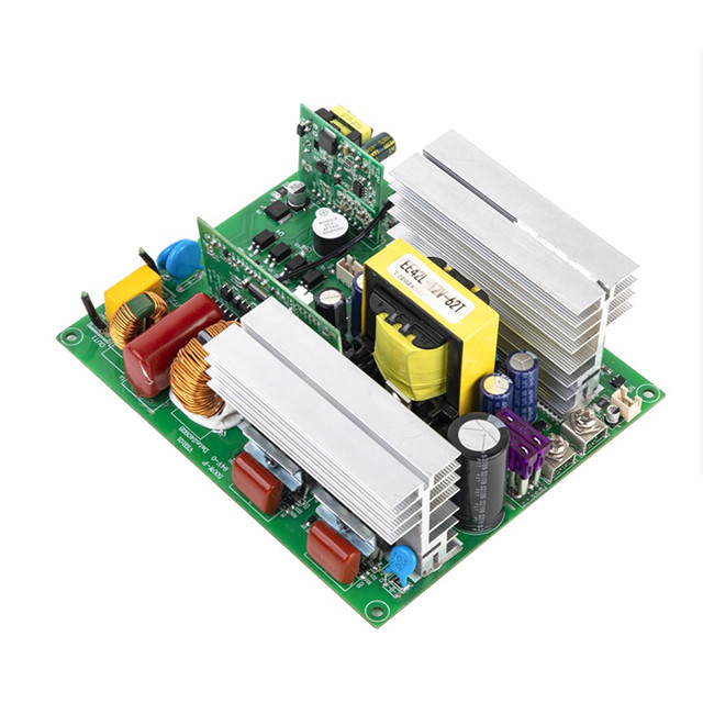
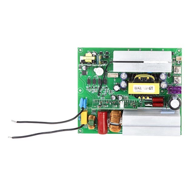
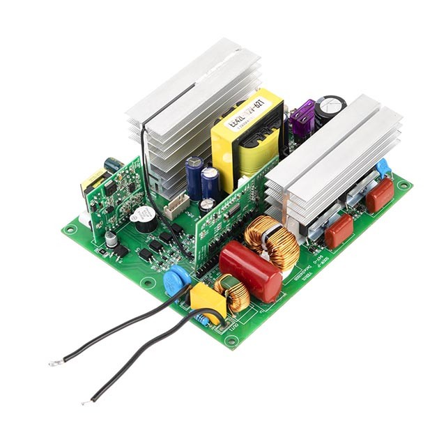
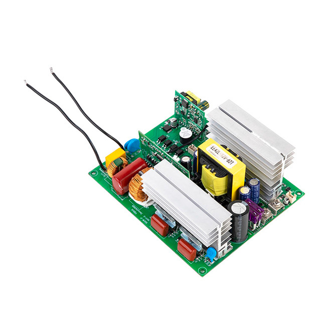
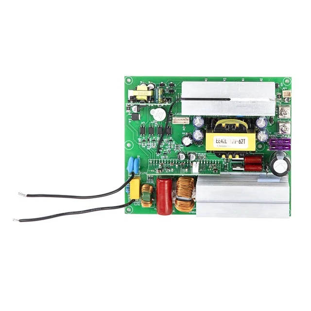
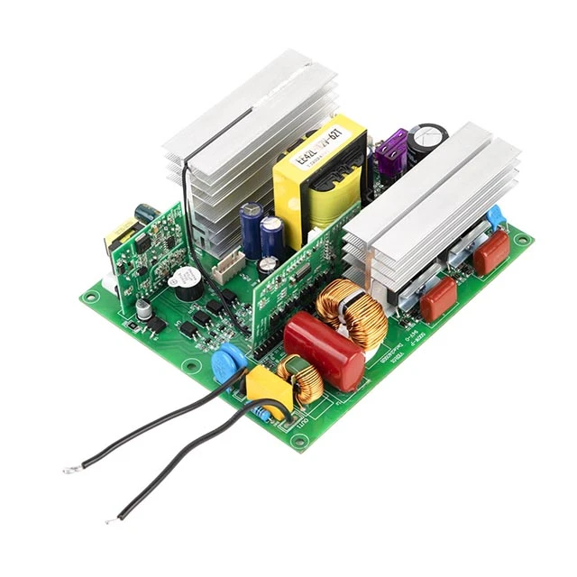
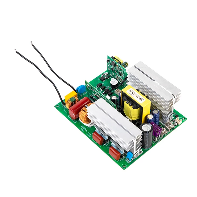
P500 · Actual product photo
|
|
|
INVERTER PCBA / FOR ENERGY STORAGE SYSTEMS
|
|
|
|
500W Pure Sine Wave
Inverter PCBA Board
|
|
|
|
ROGERELE is an OEM manufacturer of pure sine wave inverter PCBA boards for energy storage equipment. The P500 delivers 500W rated AC output and is supplied in separate 12V, 24V or 48V input configurations. For OEM projects, specify the AC output, battery operating range, cooling, mounting and accessory requirements, then validate the selected assembly with samples before bulk production.
|
|
|
|
500W
Rated output · P500
|
1000W
Listed peak output
|
|
|
|
|
DC input
|
12V / 24V / 48V configurations
|
|
AC output
|
100 / 110 / 120V or 220 / 230 / 240V
|
|
Frequency
|
50Hz or 60Hz
|
|
Dimensions
|
150 × 125 × 55 mm
|
|
|
|
|
|
|
|
|
Share your battery specification, AC load profile and order quantity.
|
|
|
|
Product Overview
The Rogerele P500 is a 500W pure sine wave inverter PCBA for OEM energy storage and custom battery-powered equipment. Separate 12V, 24V and 48V versions provide the DC-to-AC conversion stage. Listed maximum efficiency is 90%, 92% and 95% respectively, depending on version and operating conditions. Low no-load current supports efficient standby operation. Applications include off-grid battery systems and portable power equipment; RV integration requires evaluation of the battery, loads and installation. OEM/ODM requirements, including electrical configuration, mounting and accessory scope, are reviewed before sample approval and bulk production.
01 / ENERGY STORAGE INTEGRATION
Core Features & Protections
P500 provides 500W rated pure sine wave AC output, with listed THD below 3% under a linear load. The catalog lists low-voltage, over-voltage, overload and over-temperature protection, short-circuit indication and fuse operation for reverse polarity. Validate protection behavior and cooling in the complete system.
Match the inverter board to the battery and enclosure as one system. Specify charging and system-control functions separately.
01
Battery pack
Matched voltage and discharge capability
|
02 / P500
Pure sine wave inverter
500W rated AC output
|
03
Your AC loads
Continuous and startup requirements
|
|
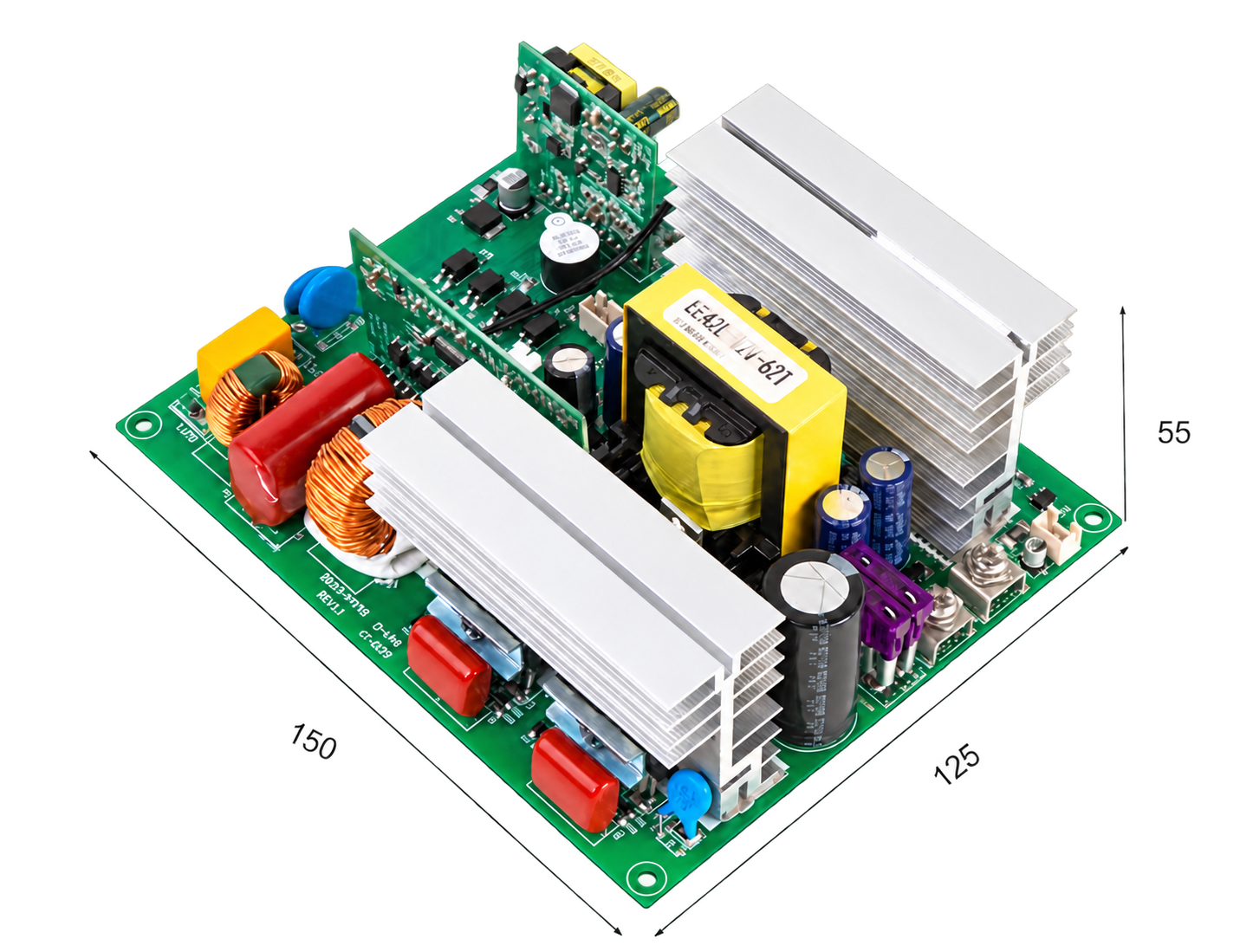
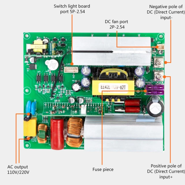
Board dimensions
150 × 125 × 55 mm
Complete board · 150 × 125 × 55 mm · Click to enlarge
|
|
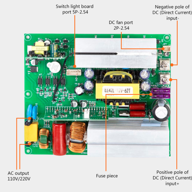
Connections & layout
Plan wiring and controls
Catalog connection reference · Click to enlarge
|
|
|
Confirm mounting-hole positions, clearance and the current board revision before enclosure design. Overall dimensions are 150 × 125 × 55 mm.
|
Integration item
|
What to specify
|
|
Battery supply
|
Pack operating-voltage range, continuous/peak discharge limits and cutoff coordination.
|
|
Charging architecture
|
Separate solar charge controller or AC charger, charging limits and system controls.
|
|
Cooling & mounting
|
Fan arrangement, airflow, mounting points, insulation and enclosure clearance.
|
|
System verification
|
Actual-load startup, thermal performance, cutoff/recovery and complete-product tests.
|
02 / TECHNICAL DATA
Technical Specifications
Select one DC input and one AC output configuration. Voltage options are order variants, rather than selectable settings on every board.
|
Parameter
|
P500 specification
|
|
Rated / peak output
|
500W / 1000W; peak duration not specified
|
|
Waveform / distortion
|
Pure sine wave · THD <3% with linear load
|
|
AC output ±5%
|
100 / 110 / 120V or 220 / 230 / 240V
|
|
Output frequency
|
50Hz ±0.5Hz or 60Hz ±0.5Hz
|
|
Operating / storage temperature
|
−10°C to +50°C / −30°C to +70°C
|
|
Listed dimensions
|
150 × 125 × 55 mm
|
Choose the battery-side configuration
|
DC input
|
Operating range
|
No-load current
|
Max. efficiency
|
|
12V
|
10–15.5V
|
<0.4A
|
90%
|
|
24V
|
20–31V
|
<0.2A
|
92%
|
|
48V
|
40–61V
|
<0.1A
|
95%
|
Maximum efficiency depends on load and conditions.
Voltage protection reference
|
Parameter
|
12V version
|
24V version
|
48V version
|
|
Low-voltage alarm
|
10.5 ±0.5V
|
21 ±0.5V
|
42 ±1V
|
|
Low-voltage cutoff
|
10 ±0.5V
|
20 ±0.5V
|
40 ±0.5V
|
|
Over-voltage cutoff
|
15.5 ±0.5V
|
31 ±0.5V
|
61 ±1V
|
|
Low-voltage recovery
|
13 ±0.5V
|
24 ±0.5V
|
48 ±1V
|
|
Over-voltage recovery
|
14.8 ±0.5V
|
29.5 ±0.5V
|
59 ±1V
|
Listed protection functions
|
Function
|
Catalog behavior
|
|
Low voltage
|
Alarm, followed by shutdown as voltage falls
|
|
Over voltage / overload
|
Red indicator and shutdown
|
|
Over temperature
|
Alarm, followed by shutdown as temperature rises
|
|
Short circuit
|
Red indicator; confirm shutdown and reset behavior
|
|
Reverse polarity
|
Fuse operation; confirm the required installation protection
|
03 / HARDWARE REFERENCE
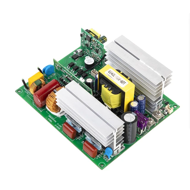
See the assembly you are evaluating.
Review the board layout and physical connections with your engineering team. Photos are configuration references; confirm the revision and included parts in your quotation.
04 / APPLICATIONS
Applications & Use Cases
Evaluate P500 as the DC-to-AC stage in energy storage, RV auxiliary power and custom power equipment. Match the battery operating range and AC loads to the selected version, then validate the complete system.
|
Application
|
What to evaluate
|
|
Portable energy storage
|
Battery capacity, AC load mix, battery discharge limits, cooling and enclosure layout.
|
|
Off-grid battery and solar storage systems
|
Battery operating range, separate solar/AC charging equipment and continuous AC demand.
|
|
Backup power for selected loads
|
Required runtime, startup demand and any separately designed transfer function.
|
|
Custom power equipment
|
For custom battery-powered equipment and mobile workstations, confirm control interfaces, mounting, cooling, accessory scope and complete-system validation.
|
|
RV auxiliary power systems
|
Evaluate battery-fed AC power for selected onboard electronics. Check continuous and startup loads, battery discharge capability, wiring, ventilation and the finished installation.
|
05 / BUSINESS SOURCING
OEM/ODM Services by Rogerele
01 / STORAGE SYSTEM BRANDS
Voltage configuration & OEM review
Select a separate 12V, 24V or 48V DC input version and specify the required AC output voltage and frequency. Submit other electrical or mechanical customization requirements for feasibility review and quotation.
|
02 / ASSEMBLY PARTNERS
PCBA & accessory matching
Define the PCBA revision, wiring, cooling fan, switch board and mounting requirements together. Confirm the supplied accessories and interfaces against your enclosure and system design.
|
03 / PURCHASING TEAMS
Sample development & bulk supply
Agree a sample configuration and acceptance criteria before bulk production. Test actual loads, thermal performance and cutoff/recovery behavior; confirm any revision scope, MOQ, lead time and required documentation.
|
|
06 / ENERGY STORAGE QUESTIONS
Answers for your system design.
How should I match this inverter PCBA with a battery BMS?
Check that the battery pack and BMS can support the inverter’s continuous input current and the load’s starting demand. Coordinate the battery operating range, discharge limits and cutoff/recovery settings with the selected 12V, 24V or 48V board. Validate startup and protection behavior in the complete system. Any communication interface between the PCBA and BMS must be confirmed separately.
|
|
What does this PCBA do in an energy storage system?
P500 provides the DC-to-AC inverter stage: it converts energy from a matched battery pack into pure sine wave AC for connected loads. The finished storage product also needs charging equipment, controls, protection and an enclosure.
|
|
|
Can it be integrated with a lithium or LiFePO4 battery?
Evaluate the pack’s minimum and maximum voltage, discharge limits and cutoff/recovery settings against the selected board. Share the battery specification for review and validate the complete system with samples; battery chemistry alone does not determine compatibility.
|
|
Does a 500W board determine the storage capacity or runtime?
500W is the rated AC output power, not battery energy capacity. Runtime depends on usable battery energy, connected load, conversion losses and system standby consumption. Verify runtime using your chosen battery pack and actual load profile.
|
|
|
Can it start pumps, fans or compressor loads?
Evaluate the load’s starting demand as well as its continuous power. The listed 1000W peak has no published duration or startup test conditions. Confirm suitability by testing the selected board and battery together with the intended load.
|
|
What should an energy storage manufacturer validate before bulk purchasing?
Confirm input/output ratings, board revision, mounting, cooling, controls and supplied accessories. Test the assembled system across battery voltage and load conditions, including startup, cutoff/recovery and thermal performance. Agree sample acceptance criteria and required product documentation before the bulk order.
|
|
|
07 / CATALOG VIDEOS
Review the existing product videos.
Use the videos as a visual reference and confirm the exact configuration and test conditions with your quotation.
Tell us about your energy storage project.
Battery pack · Discharge limits · AC loads · cooling · quantity · destination market